This tutorial was written By Andy at www.dolewalla.com.
He wrote it for his book on gmax. But the publisher made him dump it because
"Its too technical for mappers", so he withdrew this chapter (and
5 others). He's teaching mapping for UT2K3 at Art Institute of California, Los
Angeles.
The concept of this chapter is to get you to a place where you have overcome
most of the major hurdles inherent in creating a Medal of Honor (MOH) level.
Radiant is an excellent level editing tool. Originally Radiant was built for
use with Quake, now there are many flavors of Radiant, the one used for this
chapter is MOHRadiant. The exercises in this chapter lead you through creating
a simple level demonstrating the fundamental features of the editor to create
basic, essential objects. Use the techniques learned through doing the exercises
as a foundation to your knowledge of Radiant. Remember, Radiant is a leading
game editor used in many prominent games such as Soldier of Fortune and Return
to Castle Wolfenstien, Jedi Knight II, and Quake III Arena.
In this chapter the exercises show how to create a boundary ‘shell’
to define the extents of a level, how to create objects inside the boundary,
how to texture the objects, and then gives an introduction to lighting. The
compiling process is introduced as early as possible so you can test the level.
The exercises in this chapter are not going to lead you through creating a
finished level, but they do show how to create all of the main features of a
level. You can then use these features to create your own design of level. If
you want to play an example of a level made with these techniques, copy the
file mohlevel1.bsp from the \chapter12 folder on the CD-ROM into your Medal
of Honor maps folder and then load it from the console inside the game.
Installation
Game Installation
You must install the Medal of Honor game into a folder named without spaces.
This chapter uses the game folder name c:\moh
Editor Installation
You must also install the MOHRadiant editor into a folder without spaces in
the name. This chapter uses the folder name c:\mohaatools
Download and install the Medal of Honor level editor:
Download the latest version of MOHRadiant software from the official Medal
of Honor web site at http://mohaa.ea.com/
The file comes as a .zip file. You can extract this file to any folder you
like as this just extracts the installation program.
In the extraction folder, you will find a program called MOHAATOOLS.EXE.
This file is another compressed file, but in a self-extraction format (Rar).
Double clicking this file begins the extraction and installation process,
part of which asks which folder the files should extract to. You should extract
the program to a folder structure that has no spaces in the name. Do not
use the default folder (\Program Files\MOHAATools) for extraction.
At the time of writing this, the process that
converts (compiles) your level into a game readable format (.bsp files) cannot
read folder names that contain spaces. Both the editor and the game folder name
cannot contain spaces.
Summary
One folder c:\moh contains the game executable mohaa.exe. Another folder c:\MOHAATools
contains the editor.
Editor Configuration
Before you can configure the MOHRadiant editor, you must copy an Entity Definitions
file into the \main folder underneath the games folder. This file contains data
about entities (weapons, player start positions, etc) so you can create them
in a map:
With the extraction of MOHRadiant came a file called entdefs.pk3, locate
this file. Copy it to the folder called \main under the folder containing
your MOH.exe executable file. Our folder name is c:\moh\main.
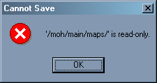
Under the \moh\main folder, create a new folder called maps. The editor
expects to find this folder to autosave your maps. If you don’t create
this folder you will get an error message as shown in figure 12.1.
Figure 12.1. Cannot autosave to the \maps folder.
Launch the editor (mohradiant.exe) from its folder and enter the information
asked for. If you want to change the information later open File/Project Settings
from the main menu in the MOHRadiant editor.
If you run into problems using the editor you may need to edit the MOHRadiant
configuration file default.qe4. MOHRadiant uses this file to find the
folders for files that it uses. The self-extraction file places default.qe4
into the same folder as the editor.
MOHRadiant uses an external program, q3map.exe,
to compile your map, default.qe4 must point to the folder which contains this
file.
Look in the folder that contains mohradiant.exe, use Notepad to open the
default.qe4 file from this folder.
Look at the contents of a default.qe4 file as shown below, change i:\moh
to your Medal of Honor root folder (the folder where moh.exe is).
The folder name directly after the parameter -gamedir (in the line "bsp_BSP"
"! q3map -v -gamedir ../moh/ $") points to the folder that contains your game
executable (mohaa.exe). This link is relative to the folder that contains mohradiant.exe.
-v means verbose response, ‘tell me everything’, responses are
sent to the console which you can open and close by pressing the o key while
in the editor.
-moddir the folder where mods are kept, not used in these exercises.
Project Settings
Taken from the Radiant Manual.
Basepath: This traces a path, beginning in your root directory to the
baseq3 where the editor expects to find resources.
Mapspath: This traces a path, beginning in your root directory, to
the location where maps are saved and from which they are loaded. The default
is the maps directory.
Rshcmd: This means "remote shell command." Use it only if you are directing
a remote processing device (not your editing computer) to compile maps. The
syntax for the field is: "rsh [processor name]"
Remotebasepath: If you are running your compile from your editing computer,
this should be the same as your basepath. If you are working off a remote compiling
device, this should trace the full path to the to the baseq3 folder where the
compiler will find the resources it requires.
Entitypath: This traces a path to the definition file for your game
entities. This can either be a .c file which contains the game code, or a .def
file which contains more instructive information about the entities.
Texturepath: This traces a path, beginning in your root directory,
to the location from which textures are loaded. The default is the textures
directory.
Tour of the MOHRadiant interface
Views
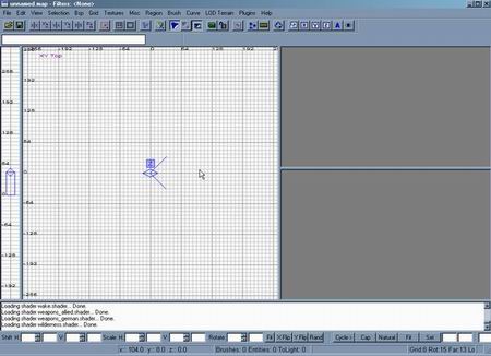
Figure 12.2. The MOHRadiant interface.
Figure 12.2 shows the entire interface. When you launch MOHRadiant you are
presented with one large View in the center the Top view looks down at your
map, a tall thin view on the left lets you change heights. Two panels on the
right, the upper panel is the Camera view, the lower panel is the Texture view.
You can resize the views by dragging the bars between them and you can change
the views from the View main menu if you choose Layout.
Alternatively, you can cycle the Top view through Side, Front, and back to
Top view by clicking the Change Views icon in the main toolbar. Figure 12.3
shows the icon.
Figure 12.3. The Change Views icon.
Zoom
Mouse wheel zooms in or out.
Insert Zooms in
Delete Zooms out
Pan
Right click and drag.
Selecting Objects
Hold the Shift key down and click an object to select it.
Shift click to de-select an object.
Escape to de-select all objects.
Backspace to delete a selected object
Moving an Object
Select an object, then click and drag from inside the selected object to
move it.
Clicking and dragging from outside an object moves the nearest edge.
Rotating an Object
The rotate icons in the rotation and mirror toolbar (Figure 12.4) rotate objects
90 degrees at a time.
Figure 12.4. Rotation and Mirror toolbar.
Use the rotation icons for 90 degree object rotations.
The trick to understanding the rotation direction is to know that the x axis
is horizontal. The label on the view tells you the vertical axis. Therefore,
if you rotate around the x axis, the top of the object will come up toward you.
The rotation group of icons also contain icons
(the ones with the red bars) used to mirror an object.
90 degree rotation example:
Select an object in the Top (XY) view.
X is horizontal, Y is vertical, so Z must come out of the screen toward
you. So click the z-axis rotate icon to rotate the object clockwise by 90
degrees.
15 degree rotation example
To rotate an object in 15 degree increments press r on your keyboard, the
object should turn purple.
Click and drag to rotate the object around an axis perpendicular to the
view. To rotate the object around another axis, change the view.
Press r to turn rotation off.
Open Preferences from the Edit main menu to
change the rotation increment.
Camera View
You can use the right mouse button to click and drag in the XY Top view
to rotate the camera. Alternatively, use the arrow keys to rotate and move
the Camera view.
For an easier time moving and rotating the camera view, click the eye icon
at the far right of the main toolbar. Then you can use the right mouse button
to rotate the view and the arrow keys to zoom. Click the eye icon again and
you get a second way of using the camera view.
The letters c and d on your keyboard move the camera down and up respectively.
Textures View
Right click and drag to move the texture window up.
Grids
The horizontal and vertical grids in each of the 2D viewports can change spacing
when you zoom a view. When creating geometry, you should try to keep corners
and edges on the grid intersections. When you design your initial level layout
bear in mind that 16 units represents 1 foot, so a grid size of 16 units lets
you create geometry accurately if you count grid lines.
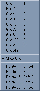
Open the Grid main menu and choose a grid snap size, figure 12.5.
Alternatively, press a number on your keyboard to change the size.
Figure 12.5. Grid snap sizes.
Changing the grid value in the Grid main menu changes the Grid Snap not the
spacing of the displayed Grid. The size that you choose determines the incremental
size of the objects that you make. If, when you create an object its edges don’t
appear to lock onto a grid intersection then the Displayed grid spacing is not
the same as the grid snap size.
Creating a Simple Level
Half the battle with many level editing programs is in configuring, successfully
compiling and testing a level. After you achieve these seemingly insurmountable
hurdles you will find that you start to have fun winning the other half of the
battle in creating the geometry of the level.
The exercises in this chapter lead you through the process of creating some
of the more interesting features in a game level. You create the boundary of
a simple level, texture it, add lighting, and make a start position for a player,
major geometry and entity types available in MOHRadiant. Additional exercises
include lighting and texturing objects.
Creating Geometry that Bounds the Level ( a sky box
)
You must make a ‘shell’ from geometry with no gaps or overlaps
to surround your level. Six brushes in a box formation is a classic and simple
way to achieve this. Later, when you gain more experience you can experiment
with more interesting boundary shapes, but for now, this tutorial illustrates
a six-brush border. The CSG Hollow tool, with one click, lets you create six
brushes from a single brush. This will ensure that the map does not ‘leak’,
a leak occurs when there is a gap in the boundary shell, see the section on
debugging.
Note:
The Grid Snap setting determines the thickness of the brushes made by CSG
Hollow.
As you create the object, watch the dimension and position readouts at the
bottom of the screen.
Create the base below zero level, then, when you use CSG Hollow tool the
top of the base will be on zero level.
Follow the steps to create a box style boundary for the level (don’t
worry too much about accuracy the subsequent section deals with changing an
objects size):
Use your mouse wheel or press the Insert and Delete keys to zoom the Top
view until you can see grid dimensions of at least -1024 to 1024 vertically.
In the Grid main menu choose Grid 64. The edges of objects that you draw
will now snap to increments of 64 units.
In the Top view, click and drag to draw a brush from -1024,-1024 to 1024,
1024. Watch the bottom of the interface for a readout of your cursor position.
After you click and drag you should see a red rectangle in the Top view.
If you missed the exact positions press Backspace to delete the object,
try it again.
Click the Change Views icon (it has XYZ in it) in the main toolbar to change
the XY Top view into the XZ Front view. You are now looking at the front of
the ‘building’.
To make the brush taller, place your cursor above the top edge (not on the
edge), click and drag to move it to a height of around 512 units.
Click and drag the bottom edge of the brush until it sits 64 units below
the horizontal 0 line.
Save the file to avoid the error message shown in figure 12.1.
With the camera inside a solid box, the camera
view displays nothing. Move the camera so that you can see the box from the
outside.
Moving Edges
Just in case you had difficulty making the exact size of the brush in the previous
section, move the edges of the brush to get the size. Moving a brush edge to
re-size the brush is a common procedure. The main trick to remember is not to
click and drag with your cursor on the edge, rather you must click and drag
from outside the edge.
Follow the steps below to fix the overlaps:
Make sure your box is selected, bright red shows selection.
Use Change Views to go back to the Top view.
Place your cursor on the right of the right edge.
Click and drag to move the edge of the brush.
Size the brush to so the corners are at -1024, -1024 at the bottom left,
and 1024, 1024 at the top right.
Using CSG Hollow
The Hollow tool replaces each side of the original brush with a separate brush.
Each new brush takes its thickness from the Grid Snap setting, in this case
64 units. However, the new brushes take their length and width from the sides
of the original brush, which means that the brushes overlap at their edges.
This is not good, although the level will compile without error messages get
into the good habit of re-aligning edges after you use the Hollow tool or avoid
Hollow altogether and draw the brushes yourself.
Perform CSG Hollow and then fix the overlapping edges:
Change back to the Top view.
Open the Grid main menu and choose Grid 64, (shortcut key 7) – just
to confirm the 64 unit grid snap setting.
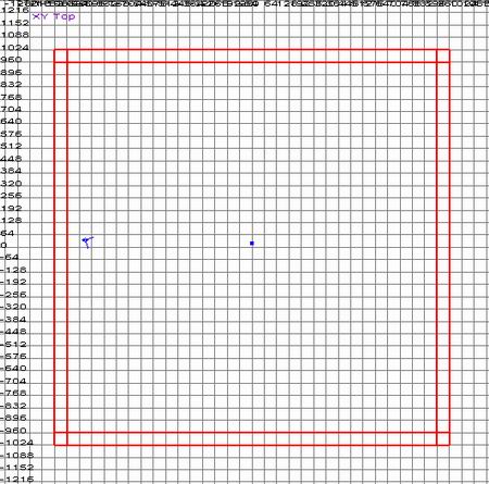
Open the Selection main menu, choose CSG from the list and then choose Make
Hollow. The single brush converts to six individual brushes as shown in figure
12.6. Fly around the inside of the boundary in the Camera view to check it
out.
Figure 12.6. Top view of a hollowed brush.
Press Escape to deselect all brushes.
Shift click to select the top brush (in the Top view). Note that shift click
selects the nearest brush.
Place your cursor to the left of the left edge.
Click and drag one grid space to bring the edge in toward the center.
Place your cursor below the lower edge, click and drag to move the edge
in one grid space toward the center.
Repeat with the other two edges.
Press the h key on your keyboard to hide the selected top brush.
Hold the Shift key down and click in the center of the objects in the Top
view. This selects the brush on the bottom, drag the edges inward one grid
space as you did for the top brush. Press h to hide this brush.
The walls also overlap. Select and hide the side walls, then reduce the
width of the remaining two walls by 64 units.
Hold the Shift key down and press the h key, this sequence (Shift + h) unhides
all hidden objects.
If your object comes off the grid, press Control
+ g to put it back on the grid intersections.
Texturing Surfaces
Texturing is the process of assigning one or more bitmaps to the surfaces of
objects in your scene. It makes sense to apply an appropriate picture for a
surface, for example a picture of bricks to go on a wall. Because MOH mostly
uses box shaped brushes, the MOHRadiant default is to apply six copies of the
texture as if the object were a box, even if it is not box shaped. However,
this increases rendering time in game.
The players in your level will never see the surface on the outside of the
boundary brushes. Wherever a player cannot see a brushes face, you should apply
a Caulk texture to that face. Or, as in the case of the Boundary brushes, apply
a Caulk texture to the entire brush and a normal texture to the inside face.
A Caulk texture is a special bitmap that tells the compiler not to include that
face in the game, thus making the game play faster. If you don’t use the
Caulk texture, the number of hidden faces in your level may slow the gameplay
until the players become frustrated and leave the level. One strategy you might
use is to apply Caulk textures as the default when you are creating objects
and then apply textures to just the visible faces. You are more likely to see
and fix a Caulk texture than you are to Caulk a hidden surface. Actually, almost
every object in your scene has some sides that the player cannot see.
Try it out, apply the Caulk texture to the boundary objects, and then choose
textures for the visible sides:
Hold the Shift key down, click all brushes in the scene.
Open the main menu Textures, choose the common category. The textures in
this category should load into the texture display panel at the lower right
of your screen.
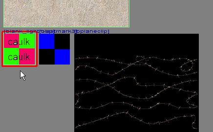
Right click and drag the texture panel up, find the Caulk texture as shown
in figure 12.7, and click it,. The texture should appear on every side of
the selected objects as shown in figure 12.8. If everything is too dark to
see, open the View main menu choose Lighting and turn Real Lighting off.
Figure 12.7. Caulk bitmap in Texture view.
Figure 12.8. Caulk Texture applied to all objects.
De-select the objects by pressing the Escape key.
Hold the Control and the Shift keys down, in the Camera view click on the
brush at the bottom of the scene (the ground brush). Only one side of the
brush turns to the red selection color.
In the Textures main menu, choose the .. item to return
to the texture categories.
Choose the misc_outside category from the Textures menu. Scroll through
the texture window and find one that you like for the ground, click the bitmap
to apply it to the selected face.
To force the picture to stretch to the size of the selected face, click
the Fit button at the bottom of the interface.
Inside the boundary you should see your selected bitmap on the ground, if you
fly your camera outside the boundary brushes you would see the Caulk texture
on the faces underneath the ground brush as shown in figure 12.9.
Figure 12.9. Caulk Texture on the outside of the objects.
Sky Texture
To create the appearance of a seamless sky, apply a sky texture to the top
and side brushes. The specially created textures from the Sky textures category
in the Textures main menu create the appearance of a continuous sky around your
level. As in the last section only select and apply bitmaps to the inside faces.
To create a sky:
Press the Escape key to deselect any selected objects.
You may find it easier to select faces from the Camera view, use right click
and drag in the Camera view. Hold the Control and Shift keys down, click every
brush except the one on the floor.
In the Textures main menu choose .. to go back to the categories
as shown in figure 12.10, scroll the list of textures, choose Sky from the
list.
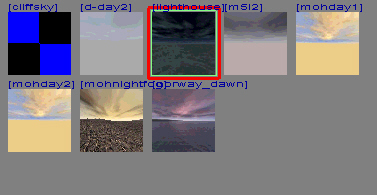
Right click and drag the Textures panel until you see a sky texture that
you like, click the texture to apply it to the faces of the selected objects.
Figure 12.10. Texture main menu.
Adding a Player Start Position
Every level requires at least one player start entity. You must place the entity
in a valid position inside the bounding boxes, if the entity is inside or touching
a brush the player may not be able to move when he enters the level.
Depending on how your computer is set up, you
may need to right-click twice to create an entity.
Follow this sequence to create a player start entity:
Press Escape to deselect all objects.
Right-click in the center of the Top view, choose info from the
list.
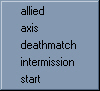
In the info panel choose player, in the player panel choose start
as shown in figure 12.11.
Figure 12.11. Player Start.
Click the Change Views icon to change the main view to a front or side view.
Move the player start entity so its lower edge is on the top of the ground
brush. Change the grid snap if you need to.
Press n to bring up the Entity window. In this dialog you can change attributes
of the selected entity.
In the white key panel next the name Key, type in angle.
Press the Tab button to move to the white Value panel, type in 180 and press
the Enter key. The key name angle and its value should appear in the
white information panel. The angle specifies the direction that the player
will face when he enters the game.
Press Escape to deselect the player start entity.
Creating Weapons
Although your basic room will compile and play without a weapon, you might
feel vulnerable without one. Weapons are in a list of Entities, which you can
bring up by right clicking in a 2D view. Just choosing an entity from the list
will create the object in the scene. You can fly around in the Camera view to
look at the object fully rendered. We will meet several types of entities as
the tutorial progresses.
Follow the steps to add a Weapon entity to your scene:
Deselect all objects by pressing the Escape key on your keyboard.
Right-click on somewhere inside the boundary.
Choose Playerweapon, a category opens so that you can choose Allied or
Axis weapons. Choose one category and weapon from that category.
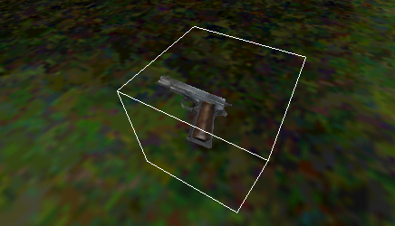
You may need to move or rotate the weapon. Checkout the object in the
Camera view, figure 12.12 shows a Camera view of a Colt 45.
Figure 12.12. Colt 45.
Creating Breakable Crates
Crates have many uses, you can use crates to hide items, you can place items
on them, and you can use them for climbing over objects. Indestructible crates
are just boxes, but you can assign a crate as breakable and set a strength value
which determines how hard you must try to break the crate.
Follow these steps to place a breakable Crate entity in your scene:
Press escape to deselect all objects.
Click and drag to draw a crate size brush.
Press n to open the Entity dialog window.
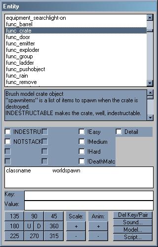
Scroll through the list in the Entity types panel, double-click the Entity
type func_crate as shown in figure 12.13. The attribute name func_crate appears
next to the object name on a correctly assigned entity.
Open the Textures main menu and choose a suitable material
for the crate. You might find something suitable under German or
das_boot.
Figure 12.13. Crate Entity.
Lighting the Scene
You must light the level so your player can see where he is going. Lights come
under the category of Entities, and each type of entity that you make has specific
attributes associated with it that you can change, for example a light would
have an intensity value assigned.
The default type of light in MOH is an omni-directional light. This type of
light shines out from a point source illuminating everything within its path.
The light travels a distance of 300 units unless you change the Entity value
key light.
Create lights in each corner of the level:
Right click on the Top view, choose Light from the entity list.
Click and drag the light into one corner of the scene.
Press the n key on your keyboard to open the Entity dialog.
In the Entity dialog, in the white panel next to the word Key type
in light.
In the white panel next to the word Value type in 2000 and press the Enter
key. The key word light and its value should appear in the white information
panel and the red radius showing the travel distance should display in the
2D views.
Press Escape to deselect.
Right click in the scene, create another light.
Move this light to another corner of the room.
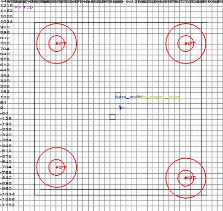
Create lights for the other corners of the level, as shown in figure 12.14.
Change their light values so that the entire scene is covered by lights but
try not to let them overlap too much or hotspots will appear.
In the Front and Side views make sure that the lights are inside the main
walls, move them if you need to. Use the Camera view to check the positions.
Figure 12.14. Lights in corners of boundary.
Make sure you de-select all objects before
creating an entity.
The explanation for the key parameters gives the light parameter as intensity,
however the light parameter is the distance traveled for the light. You will
see an outer radius shown as a red circle that indicates distance that the light
covers. The default value for the parameter light is 300, changing the parameter
and pressing Enter will increase the radius of the circle and travel of the
light.
Compiling the Level
The previous sections are slightly more than the minimum required before you
can compile and player test a level. The crate and weapon are not strictly necessary,
the texture is not required either but the Caulk texture would break the compile.
Although you can use the editors built in commands for compiling they often
cause problems and their features are largely undocumented so deciphering the
commands is difficult. The alternative to using the built in commands is to
write the command out in a command window, both methods are shown below.
Compiling from MOHRadiant
Compiling involves invoking programs from the BSP main menu. The main program
is bsp_BSP which changes the map file into .bsp type game readable format. The
second command that you call, bsp_Light (Final) calls up the MOHLIght program
and creates the lighting for the geometry.
Compile the level using compile commands from the BSP main menu:
Open the File menu and click Save, type in a name the first time that you
save the level. The file is stored in the \main\maps folder under the game
executable folder.
Open the BSP menu and choose bsp_BSP.
Open the BSP menu again and choose bsp_Light (Final)
These programs use the information stored in default.qe4 to find folders. If
any problems occur using the compile programs, open default.qe4 with a text
editor and change the settings. The information in the section about installing
the Editor at the beginning of the chapter should help you with this configuration
along with the following:
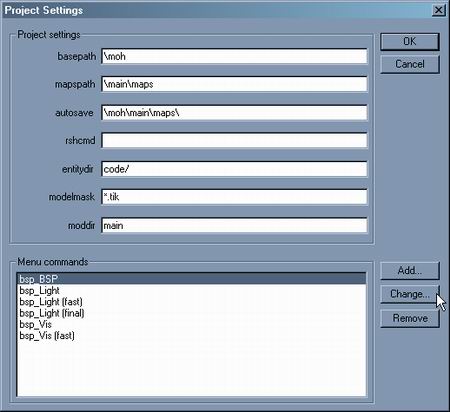
You can configure the bsp compile programs if you open the Project Settings
from the File main menu, highlight the bsp_BSP name then click the change button
as shown in figure 12.15.
Figure 12.15. Changing a bsp command.
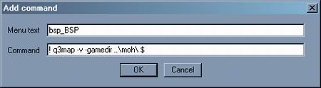
Clicking the Change button brings up the dialog shown in figure 12.16.
Figure 12.16. Changing the bsp_BSP compile command.
The line that you see in the command area is essentially the same as the command
that you create in the following section on compiling manually. You could change
this command to a fully manual command which would work around any folder errors
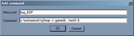
that occur with the original command. Changing the command might look like figure
12.17.
Figure 12.17. Changed command line.
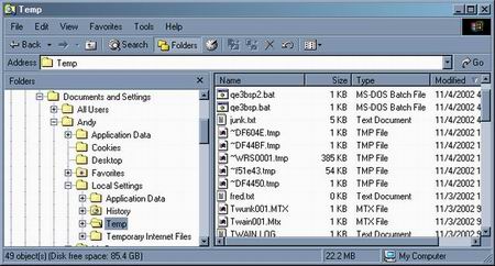
One reason why the original command line may not work is that it creates a
batch file and but cannot run it from its current folder. The batch files, sent
to your Windows temp folder are shown at the top of figure 12.18 – qe3bsp2.bat
and qe3bsp.bat.
Figure 12.18. Batch file saved by the compiler command in MOHToools.
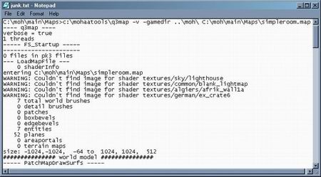
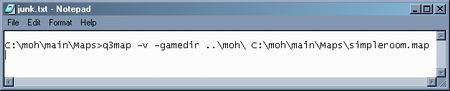
The junk.txt file that you see near the top of the files shown in figure 12.18
contains the result from using the –v option when running the batch files.
If you open it you will see the compiler output. The output looks similar to
the one shown in figure 12.19.
Figure 12.20. All is great.
If however, you see something similar to figure 12.20, then the compiler did
not work.
Figure 12.20. Compiler error.
The output shown in figure 12.20 results when
the compiler command calls the q3map program from an incorrect folder.
Compiling manually
Compiling manually is easy and gives you the most control. The command line
that you enter in a Command Prompt window is global, you only need to change
the name of the map to compile any map.
Try it out:
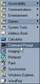
From your Windows Start menu, choose Programs and then Accessories, from
the Accessories list choose Command Prompt as shown in figure 12.21.
Figure 12.21. Invoking the Command Prompt.
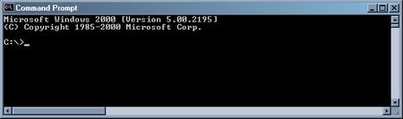
Figure 12.22 shows the Command Prompt window that opens.
Figure 12.22. Command Prompt window.
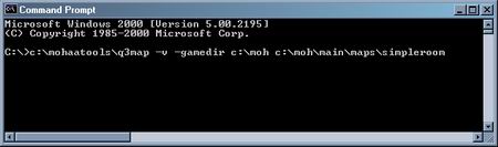
A command typed in would look like the following :
The window should look like figure 12.23. Press enter to run the command
after you type it in.
Figure 12.23. BSP Compiler command.
Explanation of the command line
C:\mohaatools\q3map – calls up the q3map compiler program from
the mohaatools folder on the c drive.
-v – A q3map option that writes out the result of the compiler
(figure 12.24 shows one correct result).
-gamedir c:\moh – Tells q3map in which folder the game executable
(mohaa.exe) resides.
C:\moh\main\maps\simpleroom – The folder and name of the map.
It is not necessary to put the .map extension on the end.
The command is not case sensitive, but you
must put the spaces in the correct places.
A batch file is a text file that runs instructions from the command prompt.
You could of course, use a text editor to create a batch file with this line
and then just run the batch file from Windows. Do this if you know how and you
can just change the name of the map. The disadvantage of this method is that
you will not see the –v (verbose) output from the batch command.
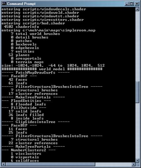
Running the batch command on the room made in the exercises results in a great
long stream of information some of which is shown in figure 12.24.
Figure 12.24. Verbose output from compiler.
Play Testing a Level
You should play test your level at every stage that you can. When you see the
scene through the players eyes you may want to change things around to improve
them.
Play test the progress on your level:
Launch Medal of Honor.
Open up the Options screen, choose Advanced. Click the Console checkbox
to enable the console in the game.
Return to the Options screen.
At the options screen, before you enter a game, bring down the console by
typing ~ (the tilda key).
Type in the words map simpleroom, or the word map and the
file name that you used to save the level.
Debugging
Say for one crazy minute that your level didn’t compile properly, here
are a few common problems with their remedies.
The level seems to compile but MOH cannot load the map.
Look in the \moh\main\maps folder for the compiled names which are test.bsp
and test.prt. If you find them somewhere else, copy them into the \main\maps
folder. Try loading the level again.
Everything is black when you enter the level.
Add lights, make sure they are near enough to the walls to shine on the
walls.
You can’t move.
The player start object is below the floor, move it up in the Front
or Side views until its lower edge is above the top edge of the brush
where he is standing. Check this by looking at the object in the Camera
view.
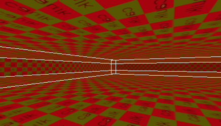
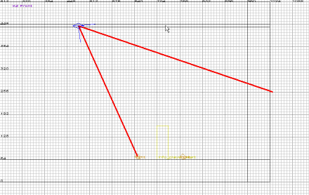
The compile process says there is a leak.
A leak is a gap between the outside walls or some part of the level
exists outside the boundary. A nasty red line will show up on your screen
when this type of gap occurs, an example is shown in figure 12.25. To
fix a leak, make sure all of the boundary walls meet each other exactly
with no overlaps. Also, move all objects inside the walls.
Figure 12.25. Compile Leak.
Improving the Level
To create custom objects you can move vertices around, to create arches you
can use the built in arch tool. Windows and doors you can make with CSG subtract
but you also need to know how to make a functioning door, one that can move.
The following exercises will build on the knowledge from the previous exercises
to improve the level.
Creating a Building
As an alternative to using the Hollow tool, create the brushes yourself. After
practice, you will find that you become fast and accurate at creating structures
from brushes. Remember that 16 units in MOHRadiant represents one foot, so a
good size for wall thickness might be 16 units. A player is 96 units high, you
might want to make the doorway at least 128 units high.
If you are not sure if the corners of your
brush are locking on to grid intersections then your grid size is too large.
You need to zoom in (watch the grid coordinates) until the grid spacing is the
same as the Grid Snap setting in the Grid main menu.
Create the walls of a building (in the corner of the boundary) from brushes,
leave a gap for a door:
In the Grid main menu change the Grid Snap to 16 units.
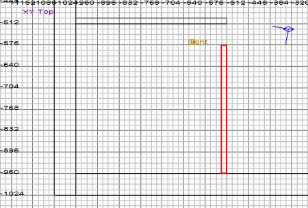
Zoom out in the Top view until you can see the bottom left ¼ of the boundary.
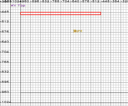
Click and drag in the Top view to draw a wall approximately 512 units sideways
but only 16 units down, as shown in figure 12.26. Watch the size readout at
the bottom of the screen as you drag. The exact position is not important,
but it is important to zoom until the spacing between gridlines shows 16 units
so that you can see where the corners of the brush lie.
Figure 12.26. Creating a Wall.
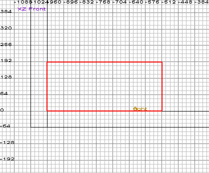
Use the Change Views icon to change to the Front View. Zoom and Pan the
view to find the brush if you need to. Click and drag the top edge of the
brush to a height of 192. Make sure the bottom edge of the brush is on the
horizontal zero line as shown in figure 12.27.
Figure 12.27. Front view of wall showing height.
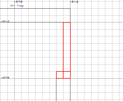
Press Escape to deselect the brush. Go back to the Top view and create another
wall parallel to the first brush, same width and depth, shown in figure 12.28.
You will find that the brush uses the height that you set for the last brush
so you don’t need to go to the Front view to change the height.
Figure 12.28. Second wall with gap for door.
Press Escape to deselect the brush.
Creating a Rotating Door
Doors in Medal of Honor typically swing away from the player when he presses
the use key within a certain distance of the door. These doors pivot around
the left or right edge of the door. The default rotating door brush made with
MOHRadiant pivots around the center of the brush. To force the door to pivot
around one edge you make an extra object and apply a special texture to it.
Then you convert the two objects together into one functional rotating door
entity. You must follow the steps of this exercise carefully otherwise, the
door may rotate incorrectly.
You must apply a special texture to the Door hinge so that it does not render,
and to tell the compiler to use its position as the rotation axis.
Follow the steps to create a door brush and a hinge brush as shown in figure
12.29:
Change the Grid Snap to 4 units.
In the Top view, zoom in to the gap between the walls at the right of the
building.
Create a door brush to fill the gap that you left in the doorway, change
to the Front or Side views and drag the top edge so that it fills the doorway.
From the Texture main menu, choose general_structure to load some general
building textures. Find and click a suitable texture for the door Brush.
Press Escape to de-select the door brush.
In the Top view, create a brush for the hinge at one end of the doorway.
Make the brush just a couple of grid squares across.
Open the Textures main menu, click up to go back to the texture category
list then, choose the Common category to load its textures.
Click the red and black Origin texture.
Press Escape to deselect the object.
Hold the Shift key down and click both the door and the hinge brush. If
something gets in your way, select it then press the h key to hide it.
Press n on the keyboard to bring up the Entity dialog.
Choose func_door_rotating from the list.
Compile the level and test the door. In the game you need to press the Enter
key to open the door, the hinge brush should not be visible.
To make the door always open away from the Player, select
the door and hinge brushes and open the Entity dialog. In the Key value
type alwaysaway and in the Value panel type in 1. Compile and test as always.
Figure 12.29. Door and Hinge Brushes.
Window Opening
Before you can put a window into a wall, you need an opening. A common way
to make an opening is to use the CSG tool. CSG will subtract the volume of one
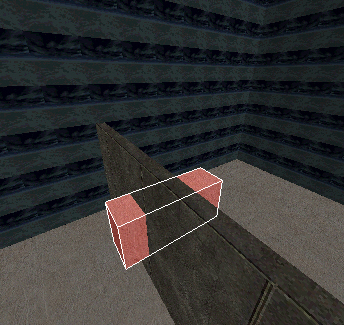
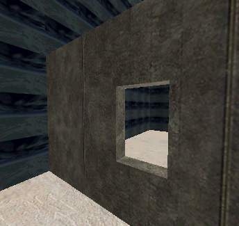
brush from another. Look at the before figure 12.30 and after Figure 12.31 pictures.
The term CSG is a little misleading, the strict technical interpretation of
CSG (Constructive Solid Geometry) implies a volumetric calculation, whereas
Radiant constructs discrete objects around the subtracting geometry. The compiling
tools are incapable of dealing with an object that has a hole in it. The end
result of this means that you must texture the resulting objects as if they
were one.
Figure 12.30. Before CSG Subtract.
Figure 12.31. After CSG Subtract.
Create a window size brush in the Front view.
Move and resize the brush in the Top view so that it protrudes (sticks out)
both sides of the wall at the right of the building.
In the Selection main menu, place your cursor over the CSG option, in the
panel that opens choose the CSG Subtract Shift+u item.
In the Top view, zoom in to the window.
Press the Backspace key on your keyboard to delete the original object.
The window opening should become visible.
You could use the object used in the CSG Subtract
to fill the gap if you resize it.
Creating the Window
Several types of window are common in MOH, solid windows which are just textures
placed on brushes, windows that you can see through but serve no other purpose,
windows that you can see through then break but not climb through and finally,
windows that you can see through, break and climb through. You create the latter
two types of window not from brushes but from entities. Each type of window
requires you to apply textures.
Create a see through, break and enter type window that fits the window opening
that you made in the last section:
Change the Grid Snap to 4.
Zoom into the window opening in the Top view.
Right click on the screen to open the entity list.
Choose the func category and then choose window from the list.
Press the n key to bring up the Entity window.
In the Key panel type in the word window.
In the Value panel type in 0 and press enter. The key name and value should
appear in the white parameters panel. Press n to close the Entity dialog.
In the Textures main menu, choose the Window category.
Double click one of the textures to apply it to the window entity.
Click and drag the center of the window object to move it into the window
opening.
Click and drag the edges of the window to make it thinner, you should find
that it snaps to grid spacing of 4 units, make the edges of the window fit
in the Front view.
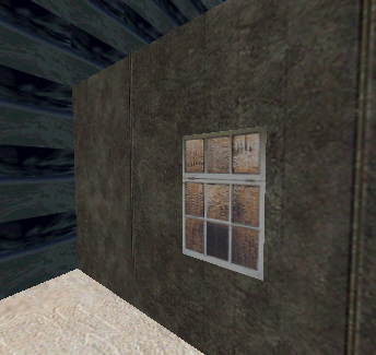
Look at the window object in the camera view, you should see something like
figure 12.32.
Figure 12.32. Window Object.
Roof
One way of making a pitched roof is to make a flat box shaped brush in the
Top view then move its left edge up in the Front view. You could then copy this
object and flip it over to make the other side of the roof.
Create a pitched roof by following these steps:
In the Top view, pan and zoom in to the top of the building.
Change the Grid Snap to 32. You will need a grid spacing that divides the
building in two.
Click and drag to draw a brush that covers half of the building.
Change to the Front view, hold the Control key down then click and drag
the left edge of the brush up.
Press the space bar to make a copy of the object.
Look in the main toolbar for the Flip Selected Brush in the X Axis icon
and click it to mirror the brush sideways.
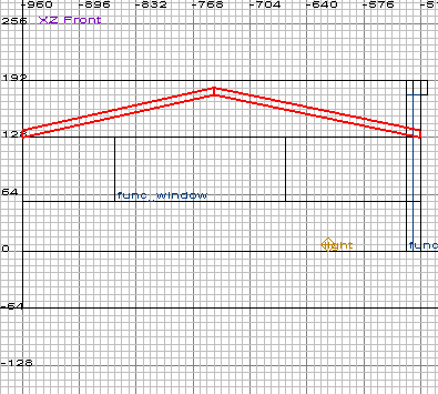
Move the object so that it matches the original roof object. The final effect
should look like figure 12.33.
Press the escape key to deselect all objects.
Figure 12.33. Half of a pitched roof.
Gable
To create the Gable (the triangular shape that fills the end of the pitched
roof), create a triangular object and then resize, rotate, and move it into
place. You can create brushes with odd numbers of faces by drawing the brush
first then opening the main menu Brush and choosing the number of faces for
the brush.
Try it out:
In the Top view click and drag to create a brush that is roughly half the
size of the front wall of the building.
In the Brush main menu choose the 3 Sided option. The brush will turn into
a triangular brush.
Use the Flip icons at the top left of the main toolbar to rotate the object.
Look at the view name to see which axis to use, remember that x is usually
horizontal and the other axis is vertical in the view.
When the gable is roughly in place, click and drag the lower corners to
put them in the corners of the roof.
Move the object and resize it by dragging its edges.
Open the Selection main menu, choose the Drag item then choose Vertices
from the small panel that opens.
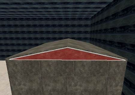
Click and drag the small green vertex on the top of the triangular brush,
place it just inside the apex of the roof. You will need to do this once more
as there are vertices at the front and back of the triangular brush. Your
gable should look something like the one shown in figure 12.34.
Figure 12.34. Gable.
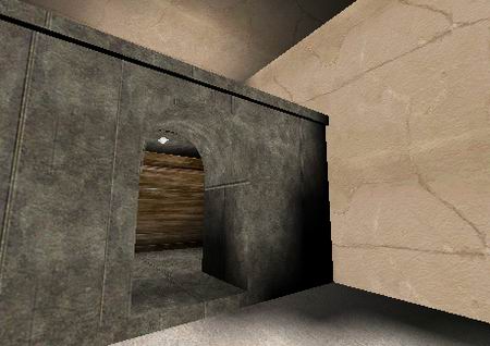
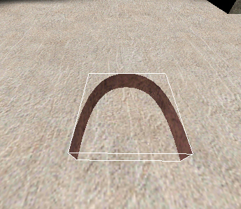
Arches
Arches are a nice feature to add to your map. Creating an arch (figure 12.35)
is easy when you know how.
Figure 12.35. An arch.
Follow the steps below to create the two parts of an arch:
Draw a brush.
In the Curves main menu open Primitives and choose End Cap. Your brush should
turn into a flat curved plane, as in figure 12.36.
Figure 12.36. End Cap.
Open the Curves main menu again, choose Cap and then Inverted End Cap, using
this option forms the surrounding exterior of the curved panel as shown in
figure 12.37.
Figure 12.37. Grouped Inverted End Cap, with End Cap.
Using the axis icons in the main toolbar rotate the brush the orientation
that you need.
Move the brush into position and resize it if required.
Create brushes that surround the arch as shown in figure 12.35.
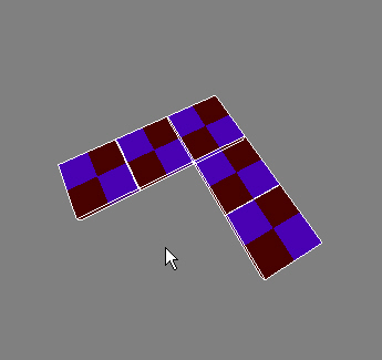
Distorting Brushes
to Create Rounded Geometry
When you want to make curved looking geometry place several brushes together
then distort their corners. Say you made the brushes shown in figure 12,38,
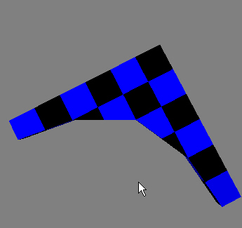
you could distort their corners so they look like figure 12.39.
Figure 12.38. 5 Brushes.
Figure 12.39. Vertices moved on 5 Brushes.
Try it out:
In the top view, create five brushes, one in the corner and two on either
side.
Hold the Shift key down, click one of the five boxes to select it.
Press v on your keyboard to display vertices on the brush.
Move the small green dots around to form a curved looking corner in a corner,
remember that there are two vertices (one under the other) at each corner
of the box.
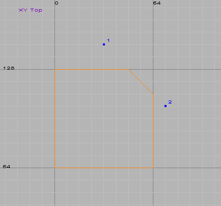
Clipping an Object
When you want to put a chamfer on the corner of an object use the Clipping
tool.
Clipping example:
Create and select a brush.
Open the Selection main menu or press x on your keyboard.
Click above one edge of the brush. The number 1 should appear at the click
position.
Click half way up and to the right of the object, the number 2 should appear,
see figure 12.40.
Press the Enter key to clip the object.
Figure 12.40. Clipping numbers.
Creating Patches
Patches are the only truly curved geometry in MOH. They are also flat one sided
objects. Make them large and chunky, patches can contain large numbers of faces
that slow your level to a crawl. When you want a sloping bank up to a wall use
a patch, if you make the slope steep the player cannot climb up the slope. This
is one way of sealing off the boundary of your level.
Just click to select at vertex level, hold
the Control key to select more than one vertex.
Try creating and manipulating a patch in one corner of your level:
Zoom in to one corner of your level in the Top view.
Click and drag to draw a brush.
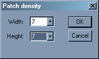
Open the Curve main menu and choose Simple Patch Mesh. A small dialog pops
up (shown in figure 12.41) asking for the density of the Patch, higher numbers
contain more faces, choose a number for the Width and Height density values.
Figure 12.41. Simple Patch Mesh density.
Click OK, the brush is now a flat, one sided patch.
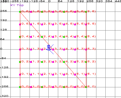
Press your v button to display the vertices on the patch
as shown in figure 12.42.
Figure 12.42. Vertices on a Patch.
Click a vertex, it should turn blue, use the Camera, Front or Side views
to move the vertex.
Hold Shift and Control to select a row or column of vertices.
Summary
Once you get the editor set up and running smoothly, MOH Editing becomes a
real pleasure. The superb range of textures and models that you can use in a
scene turns even a simple map into a polished looking, fun level. This chapter
only scratched the surface of what you can achieve with MOHRadiant.

 At the time of writing this, the process that
converts (compiles) your level into a game readable format (.bsp files) cannot
read folder names that contain spaces. Both the editor and the game folder name
cannot contain spaces.
At the time of writing this, the process that
converts (compiles) your level into a game readable format (.bsp files) cannot
read folder names that contain spaces. Both the editor and the game folder name
cannot contain spaces.